← EXPLODED VIEWP06
COMPONENT TECHNICAL DOSSIER
Snowflake Base
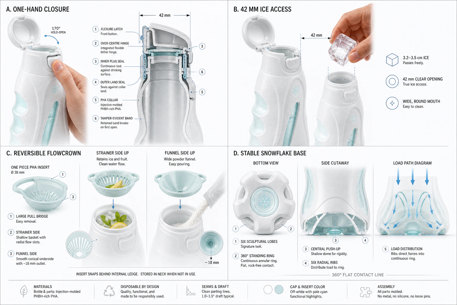
The six-lobe signature must not create instability: the visual form is subordinate to a genuine standing ring.
PRE-INDUSTRIAL R2CONTINUOUS STANDING RING
01 · PRINCIPLE & RATIONALE
Intended function
and associated requirement.
The six-lobe signature must not create instability: the visual form is subordinate to a genuine standing ring.
The bottle remains steady on a worktop, in a refrigerator and in a case, while its body profile resists rolling when laid on its side.
Retains the six-lobe signature while standing on a continuous anti-rocking ring. Six radial ribs converge on the push-up; a continuous 360° ring defines the contact plane and separates visual identity from static performance. Rocking and the limit angle on an inclined plane must be measured on full and empty samples; a rendering does not demonstrate stability.
02 · TECHNOLOGY STACK
Technologies, roles
and approval gates.
Continuous standing ring
- Role
- Defines a true 360° contact plane.
- Why
- Separates stability from the six-lobe visual signature.
- Approval gate
- Standing-plane, rocking and inclined-plane tests.
Six radial ribs
- Role
- Carry load from the body to the push-up.
- Why
- Distribute top-load and impact without separate feet.
- Approval gate
- CAE, wall map and base drop.
Central push-up
- Role
- Manages pressure, deformation and base cooling.
- Why
- Avoids an unstable centre and controls forming memory.
- Approval gate
- Tooling DOE and post-ageing flatness.
03 · ARCHITECTURE
Function, material
and interfaces.
Six radial ribs converge on the push-up; a continuous 360° ring defines the contact plane and separates visual identity from static performance.
- Six body ribs
- central push-up
- 01Continuous standing ring
- 02Central push-up
- 03Ribs connected to the body
- 04Visual signature without separate feet
04 · MASTER PARAMETER REGISTER
Everything to be defined,
measured or certified.
A field without evidence is never filled with an invented number: it remains “To be determined”, together with the method required to close it. This is what makes the technical record verifiable.
DESIGN BASISTARGETCALCULATED / MEASUREDTO BE VALIDATEDCERTIFICATION REQUIRED
01Identification & function3 PARAMETERS
| ID | Parameter | Symbol | Value | Unit | Tolerance | Condition | Method | Status |
|---|---|---|---|---|---|---|---|---|
| P06-001 | Assembly code | ID | P06 | — | To be defined | 23 °C / 50% RH unless noted | CAD, CAE or dedicated test | DESIGN BASIS |
| P06-002 | Designation | NAME | Snowflake Base | — | To be defined | 23 °C / 50% RH unless noted | CAD, CAE or dedicated test | DESIGN BASIS |
| P06-X001 | Intended use | USE | To be determined | — | To be defined | Full use cycle | Design review + user study | TO BE VALIDATED |
02Risk & maturity2 PARAMETERS
| ID | Parameter | Symbol | Value | Unit | Tolerance | Condition | Method | Status |
|---|---|---|---|---|---|---|---|---|
| P06-003 | Architecture revision | REV | R2 | — | To be defined | 23 °C / 50% RH unless noted | CAD, CAE or dedicated test | DESIGN BASIS |
| P06-004 | Technology readiness | TRL | 2–3 | level | To be defined | 23 °C / 50% RH unless noted | CAD, CAE or dedicated test | TO BE VALIDATED |
03Food contact2 PARAMETERS
| ID | Parameter | Symbol | Value | Unit | Tolerance | Condition | Method | Status |
|---|---|---|---|---|---|---|---|---|
| P06-005 | Declaration of Compliance | DoC | required | document | To be defined | 23 °C / 50% RH unless noted | CAD, CAE or dedicated test | CERTIFICATION REQUIRED |
| P06-X007 | Overall and specific migration | MIG | To be determined | mg/kg | Applicable limits | Simulant/time/temperature | Accredited methods | TO BE VALIDATED |
04Quality control2 PARAMETERS
| ID | Parameter | Symbol | Value | Unit | Tolerance | Condition | Method | Status |
|---|---|---|---|---|---|---|---|---|
| P06-006 | Lot traceability | LOT | 100 | % | To be defined | 23 °C / 50% RH unless noted | CAD, CAE or dedicated test | TARGET |
| P06-X006 | Process capability | Cpk | To be determined | — | Target to be defined | Critical CTQ | SPC ≥30 samples | TO BE VALIDATED |
05Geometry & metrology4 PARAMETERS
| ID | Parameter | Symbol | Value | Unit | Tolerance | Condition | Method | Status |
|---|---|---|---|---|---|---|---|---|
| P06-007 | Number of lobes | nlobe | 6 | no. | To be defined | 23 °C / 50% RH unless noted | CAD, CAE or dedicated test | DESIGN BASIS |
| P06-008 | Number of radial ribs | nrib | 6 | no. | To be defined | 23 °C / 50% RH unless noted | CAD, CAE or dedicated test | DESIGN BASIS |
| P06-009 | Contact surface | RING | 360 | ° | To be defined | 23 °C / 50% RH unless noted | CAD, CAE or dedicated test | DESIGN BASIS |
| P06-X002 | Nominal mass | m | To be determined | g | To be defined | 23 °C / 50% RH | Balance 0.001 g | TO BE VALIDATED |
06Mechanical properties3 PARAMETERS
| ID | Parameter | Symbol | Value | Unit | Tolerance | Condition | Method | Status |
|---|---|---|---|---|---|---|---|---|
| P06-010 | Maximum rocking | ROCK | to be measured | mm | To be defined | 23 °C / 50% RH unless noted | CAD, CAE or dedicated test | TO BE VALIDATED |
| P06-011 | Inclined-plane stability | TILT | to be measured | ° | To be defined | 23 °C / 50% RH unless noted | CAD, CAE or dedicated test | TO BE VALIDATED |
| P06-X005 | Drop resistance | Hdrop | To be determined | m | To be defined | Defined orientations | Instrumented drop test | TO BE VALIDATED |
07Manufacturing process1 PARAMETERS
| ID | Parameter | Symbol | Value | Unit | Tolerance | Condition | Method | Status |
|---|---|---|---|---|---|---|---|---|
| P06-012 | Base wall distribution | TBASE | from CAE | mm | To be defined | 23 °C / 50% RH unless noted | CAD, CAE or dedicated test | SIMULATION |
08Material1 PARAMETERS
| ID | Parameter | Symbol | Value | Unit | Tolerance | Condition | Method | Status |
|---|---|---|---|---|---|---|---|---|
| P06-X003 | Commercial grade and supplier | GRADE | To be determined | — | Qualified grade | Production lot | CoA + traceability | TO BE VALIDATED |
09Thermal properties1 PARAMETERS
| ID | Parameter | Symbol | Value | Unit | Tolerance | Condition | Method | Status |
|---|---|---|---|---|---|---|---|---|
| P06-X004 | Service-temperature range | Tservice | To be determined | °C | To be defined | Use and transport | Climate chamber | TO BE VALIDATED |
10Recyclability1 PARAMETERS
| ID | Parameter | Symbol | Value | Unit | Tolerance | Condition | Method | Status |
|---|---|---|---|---|---|---|---|---|
| P06-X008 | Territory-specific end-of-life route | EOL | To be determined | — | Country/area defined | Complete assembly | Infrastructure mapping | TO BE VALIDATED |
05 · INDUSTRIALISATION
From material
to final inspection.
Qualified material
Integral to the AQUA-PHA body
Process within window
Formed in the body mould
Controlled interfaces
Six body ribs · central push-up
CTQ + traceability
Wall distribution, cooling and flatness depend on the body mould. Standing-plane testing and CAE must guide the radii before tooling.
06 · DVP&R
A function is approved
only after passing its test.
| Test | Requirement | Risk | Method | Condition | Samples | Acceptance | Output |
|---|---|---|---|---|---|---|---|
| DVP-02 | Wall-thickness map | Weak zones | Micro-CT | 3 lots | 15 | Conforms to frozen CAE | Thickness map |
| DVP-03 | Top/side load | Collapse | Compression | 23 °C; empty/full | 30+30 | ≥250 N / ≥80 N | Force-displacement curves |
| DVP-04 | Filled-bottle drop | Breakage/leak | Drop | 1 m; water 4 °C; base/side/cap | 60 | 0 leaks; 0 loose parts | Failure map |
| DVP-10 | Base rocking | Instability | Standing-plane | Full/empty | 30 | Limit to be frozen | Rocking map |
07 · FAILURE MODES
Failure modes,
causes and controls.
Body brittleness
EffectBreakage/leak
CausePHA thermal window
ControlDSC/TGA, rheology, process DOE
Non-uniform walls
EffectBuckling/drop failure
CauseAsymmetric geometry
ControlBlow-moulding CAE + micro-CT
AeroSkin detachment
EffectLoss of function/loose part
CauseInsufficient seal
ControlPeel, thermal cycling and drop
08 · EVIDENCE POLICY
Traceability
for every parameter.
The base is integral to the body and adds no separate material. Lightweighting must not compromise stability, drainage or transport resistance.
This page is the technical register for the R2 configuration. It separates design values, targets, calculations, measurements and certifications. Open fields identify the exact test or document required to close them.