← EXPLODED VIEWP05
COMPONENT TECHNICAL DOSSIER
Reversible FlowCrown
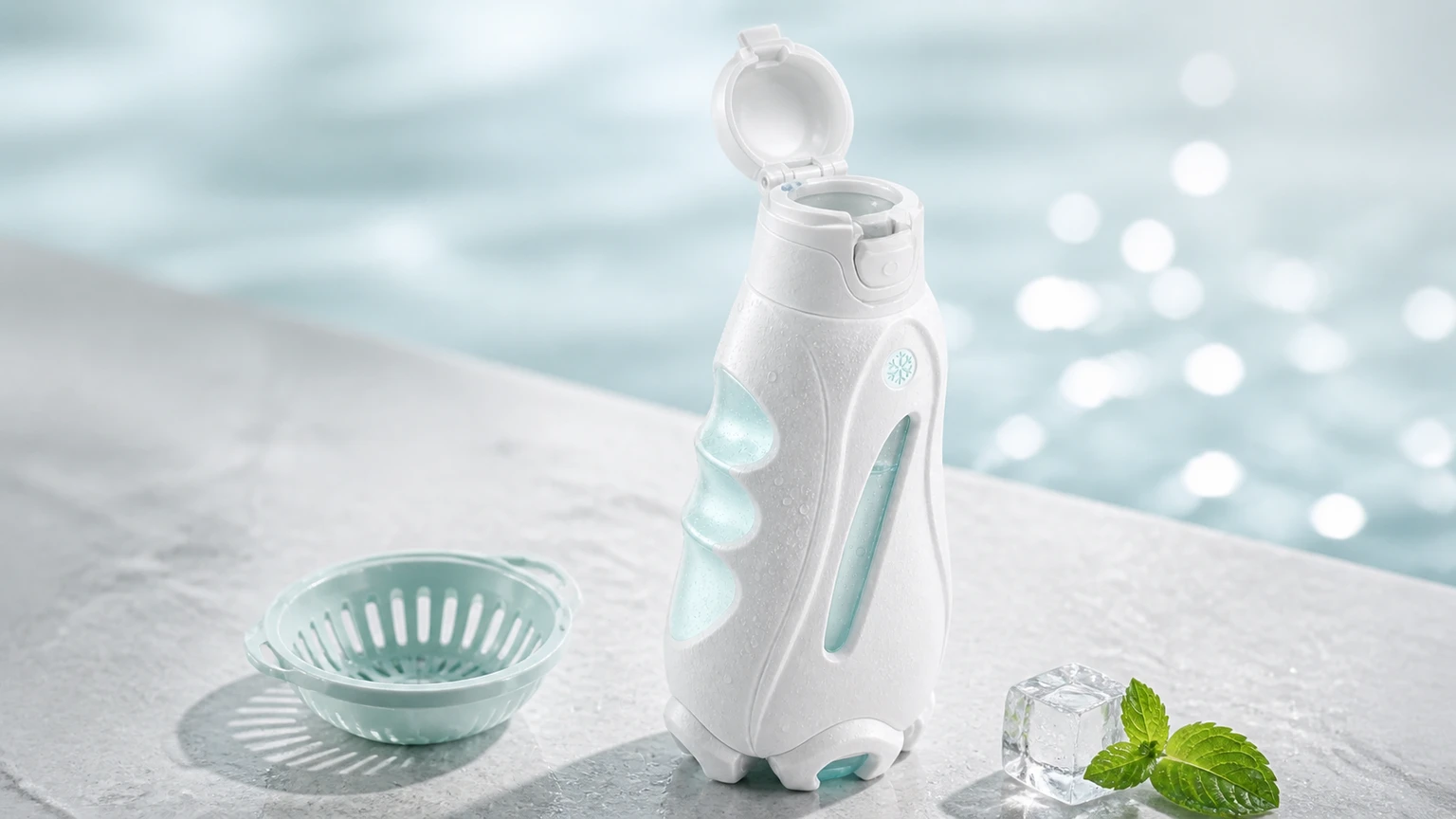
One macro-insert performs two opposing tasks: retaining solids while drinking and guiding powders during preparation.
PRE-INDUSTRIAL R2FILTER / FUNNEL INSERT
01 · PRINCIPLE & RATIONALE
Intended function
and associated requirement.
One macro-insert performs two opposing tasks: retaining solids while drinking and guiding powders during preparation.
Fruit, mint and ice remain controlled; reversing the part lets supplements and flavourings enter without a separate funnel.
One reversible macro-insert acts as a filter for solids and a funnel for powders. The concave basket snaps below the drinking rim. In the reverse orientation, its conical surface guides material towards an approximately 18 mm outlet. Flow rate, retention and behaviour with real foods have not been measured; the insert is not a microbiological filter.
02 · TECHNOLOGY STACK
Technologies, roles
and approval gates.
Reversible macro-insert
- Role
- Works as a filter in one direction and a funnel in the other.
- Why
- Replaces two accessories without small parts.
- Approval gate
- Flow, dosing and user study.
Under-rim snap
- Role
- Retains the part without obstructing drinking.
- Why
- Preserves wide access and retention safety.
- Approval gate
- Insertion/removal force and drop.
Radial flow channels
- Role
- Distribute water around ice, fruit or powders.
- Why
- Reduce blockage and splashing while preserving cleanability.
- Approval gate
- Flow rig with real solids.
03 · ARCHITECTURE
Function, material
and interfaces.
The concave basket snaps below the drinking rim. In the reverse orientation, its conical surface guides material towards an approximately 18 mm outlet.
- Internal neck snap
- entirely below the rim
- 01Basket below the rim
- 02Internal neck snap
- 03Reversible geometry
- 0432–35 mm ice cube without insert
04 · MASTER PARAMETER REGISTER
Everything to be defined,
measured or certified.
A field without evidence is never filled with an invented number: it remains “To be determined”, together with the method required to close it. This is what makes the technical record verifiable.
DESIGN BASISTARGETCALCULATED / MEASUREDTO BE VALIDATEDCERTIFICATION REQUIRED
01Identification & function5 PARAMETERS
| ID | Parameter | Symbol | Value | Unit | Tolerance | Condition | Method | Status |
|---|---|---|---|---|---|---|---|---|
| P05-001 | Assembly code | ID | P05 | — | To be defined | 23 °C / 50% RH unless noted | CAD, CAE or dedicated test | DESIGN BASIS |
| P05-002 | Designation | NAME | FlowCrown | — | To be defined | 23 °C / 50% RH unless noted | CAD, CAE or dedicated test | DESIGN BASIS |
| P05-009 | Use configurations | npos | 2 | no. | To be defined | 23 °C / 50% RH unless noted | CAD, CAE or dedicated test | DESIGN BASIS |
| P05-010 | Separate small parts | nsmall | 0 | parts | To be defined | 23 °C / 50% RH unless noted | CAD, CAE or dedicated test | DESIGN BASIS |
| P05-X001 | Intended use | USE | To be determined | — | To be defined | Full use cycle | Design review + user study | TO BE VALIDATED |
02Risk & maturity2 PARAMETERS
| ID | Parameter | Symbol | Value | Unit | Tolerance | Condition | Method | Status |
|---|---|---|---|---|---|---|---|---|
| P05-003 | Architecture revision | REV | R2 | — | To be defined | 23 °C / 50% RH unless noted | CAD, CAE or dedicated test | DESIGN BASIS |
| P05-004 | Technology readiness | TRL | 2–3 | level | To be defined | 23 °C / 50% RH unless noted | CAD, CAE or dedicated test | TO BE VALIDATED |
03Food contact2 PARAMETERS
| ID | Parameter | Symbol | Value | Unit | Tolerance | Condition | Method | Status |
|---|---|---|---|---|---|---|---|---|
| P05-005 | Declaration of Compliance | DoC | required | document | To be defined | 23 °C / 50% RH unless noted | CAD, CAE or dedicated test | CERTIFICATION REQUIRED |
| P05-X007 | Overall and specific migration | MIG | To be determined | mg/kg | Applicable limits | Simulant/time/temperature | Accredited methods | TO BE VALIDATED |
04Quality control3 PARAMETERS
| ID | Parameter | Symbol | Value | Unit | Tolerance | Condition | Method | Status |
|---|---|---|---|---|---|---|---|---|
| P05-006 | Lot traceability | LOT | 100 | % | To be defined | 23 °C / 50% RH unless noted | CAD, CAE or dedicated test | TARGET |
| P05-013 | Post-drop retention | RET | 0 detachments | — | To be defined | 23 °C / 50% RH unless noted | CAD, CAE or dedicated test | TARGET |
| P05-X006 | Process capability | Cpk | To be determined | — | Target to be defined | Critical CTQ | SPC ≥30 samples | TO BE VALIDATED |
05Geometry & metrology3 PARAMETERS
| ID | Parameter | Symbol | Value | Unit | Tolerance | Condition | Method | Status |
|---|---|---|---|---|---|---|---|---|
| P05-007 | Outer diameter | Dfc | ≈38 | mm | To be defined | 23 °C / 50% RH unless noted | CAD, CAE or dedicated test | TARGET |
| P05-008 | Funnel outlet | Dfunnel | ≈18 | mm | To be defined | 23 °C / 50% RH unless noted | CAD, CAE or dedicated test | TARGET |
| P05-X002 | Nominal mass | m | To be determined | g | To be defined | 23 °C / 50% RH | Balance 0.001 g | TO BE VALIDATED |
06Kinematics / sealing / barrier1 PARAMETERS
| ID | Parameter | Symbol | Value | Unit | Tolerance | Condition | Method | Status |
|---|---|---|---|---|---|---|---|---|
| P05-011 | Ice cube without insert | Dice | 32–35 | mm | To be defined | 23 °C / 50% RH unless noted | CAD, CAE or dedicated test | DESIGN BASIS |
07Mechanical properties2 PARAMETERS
| ID | Parameter | Symbol | Value | Unit | Tolerance | Condition | Method | Status |
|---|---|---|---|---|---|---|---|---|
| P05-012 | Insertion/removal force | Fret | to be validated | N | To be defined | 23 °C / 50% RH unless noted | CAD, CAE or dedicated test | TO BE VALIDATED |
| P05-X005 | Drop resistance | Hdrop | To be determined | m | To be defined | Defined orientations | Instrumented drop test | TO BE VALIDATED |
08Material1 PARAMETERS
| ID | Parameter | Symbol | Value | Unit | Tolerance | Condition | Method | Status |
|---|---|---|---|---|---|---|---|---|
| P05-X003 | Commercial grade and supplier | GRADE | To be determined | — | Qualified grade | Production lot | CoA + traceability | TO BE VALIDATED |
09Thermal properties1 PARAMETERS
| ID | Parameter | Symbol | Value | Unit | Tolerance | Condition | Method | Status |
|---|---|---|---|---|---|---|---|---|
| P05-X004 | Service-temperature range | Tservice | To be determined | °C | To be defined | Use and transport | Climate chamber | TO BE VALIDATED |
10Recyclability1 PARAMETERS
| ID | Parameter | Symbol | Value | Unit | Tolerance | Condition | Method | Status |
|---|---|---|---|---|---|---|---|---|
| P05-X008 | Territory-specific end-of-life route | EOL | To be determined | — | Country/area defined | Complete assembly | Infrastructure mapping | TO BE VALIDATED |
05 · INDUSTRIALISATION
From material
to final inspection.
Qualified material
Injection-mouldable PHA
Process within window
Injection moulding
Controlled interfaces
Internal neck snap · entirely below the rim
CTQ + traceability
Injection moulding and the under-rim snap require a force window that enables assembly without detachment during a drop or in use.
06 · DVP&R
A function is approved
only after passing its test.
| Test | Requirement | Risk | Method | Condition | Samples | Acceptance | Output |
|---|---|---|---|---|---|---|---|
| DVP-04 | Filled-bottle drop | Breakage/leak | Drop | 1 m; water 4 °C; base/side/cap | 60 | 0 leaks; 0 loose parts | Failure map |
| DVP-09 | FlowCrown | Detachment/blockage | Flow + retention | Ice/fruit/powders | 30 | Full function; 0 detachments | Flow rate + video |
| DVP-12 | Food contact | Migration/NIAS | Overall/specific migration | Cold-fill water use | 3 lots | Applicable regulatory compliance | Signed report |
07 · FAILURE MODES
Failure modes,
causes and controls.
Body brittleness
EffectBreakage/leak
CausePHA thermal window
ControlDSC/TGA, rheology, process DOE
Non-uniform walls
EffectBuckling/drop failure
CauseAsymmetric geometry
ControlBlow-moulding CAE + micro-CT
AeroSkin detachment
EffectLoss of function/loose part
CauseInsufficient seal
ControlPeel, thermal cycling and drop
08 · EVIDENCE POLICY
Traceability
for every parameter.
One markable macro-part replaces meshes, springs and small components. The concept targets the same PHA family, but retention and sortability must be verified.
This page is the technical register for the R2 configuration. It separates design values, targets, calculations, measurements and certifications. Open fields identify the exact test or document required to close them.